Walking Robot
Simple 4-legged Walking Robot
The Sesame Robot is an open-source, 4 legged (8 DOF), walking robot, designed by Dorian Todd. The platform is compact with a footprint of less than 20x20cm, low-cost at under $100, and personable, with its screen and gestures bringing a unique charm to the design.
I first discovered the design through a YouTube video, and immediately wanted to build my own. After convincing a friend to join in on the fun, we ordered the parts and got to work.
The project involves:
- CAD & 3D-printing.
- Electronics & Soldering.
- C/C++ programming through Arduino IDE.
This page will cover the build process, problems, developments, results, and future plans for the robot.
Build Process
BOM
The robot consists of:
| Component | Qty |
|---|---|
| 3D Printed Parts | 11 |
| MG90 Servo Motors | 8 |
| S2-mini ESP32 Microcontroller | 1 |
| 0.96" OLED Screen | 1 |
Electronics & Wiring
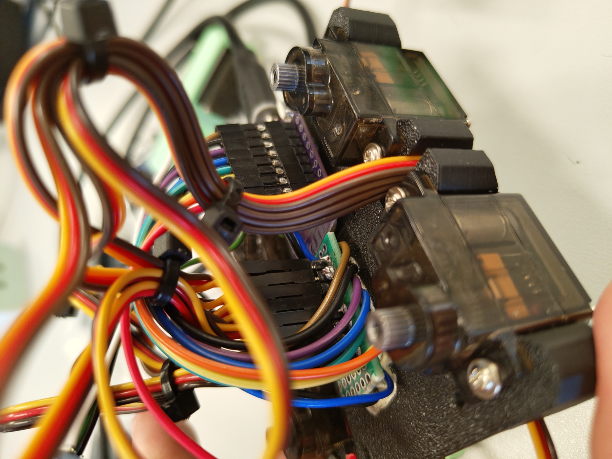
The wiring is relatively straightforward. An 8×3 pin header grid is used for the servos, with PWM signals routed to female headers (rainbow-colored wires in the second image) for easy connection to the microcontroller.
When soldering, note that the yellow wires on the servo motors correspond to the PWM signal. The 5 V and GND connections are blue (used in place of red) and black, respectively, as shown in the first image.
The display is connected via the two data lines, SDA(white) and SCL(green), and is powered using 5 V and GND supplied from the prototyping board.

The microcontroller can be powered either via USB-PD or through the 5 V pin. The 5 V pin may be supplied by a battery pack, and there is currently space for one inside the robot’s body (between the bottom cover and the main frame). This has not yet been implemented due to the additional components required, including wiring, a buck converter, and a power switch.
At present, the robot is powered through USB. While this functions adequately, USB-PD is necessary because the system can draw up to 3 A at 5 V under load, exceeding the 0.5-1 A typically available from a standard USB port. With a standard USB connection, the robot may still power on but can experience brownouts, resets, reduced performance, or failure to move under load.
For future iterations, a custom PCB hat would improve wiring organization and simplify assembly. Although Dorian Todd has designed a suitable PCB, manual soldering was chosen in this case to avoid additional cost and shipping time.
CAD & 3D Printing
Most of the CAD work was already done, but some modifications were needed for fit and assembly. Some areas were mild inconveniences:
- Undersized holes for self threading screws
- Walls too thin to print in two corners
- Print warping
Others were more significant:
- Femur joints rubbing against the body due to small tolerances, causing extra load and potential burnout of servo motors.
- Servo to servo-horn splined interface not aligning to 90°, with no modelled room for rotation.
- Coplanarity tolerance in femur joints causes wobble and three-point contact due to slight angular differences between legs, also resulting in a skewed or turning gait.
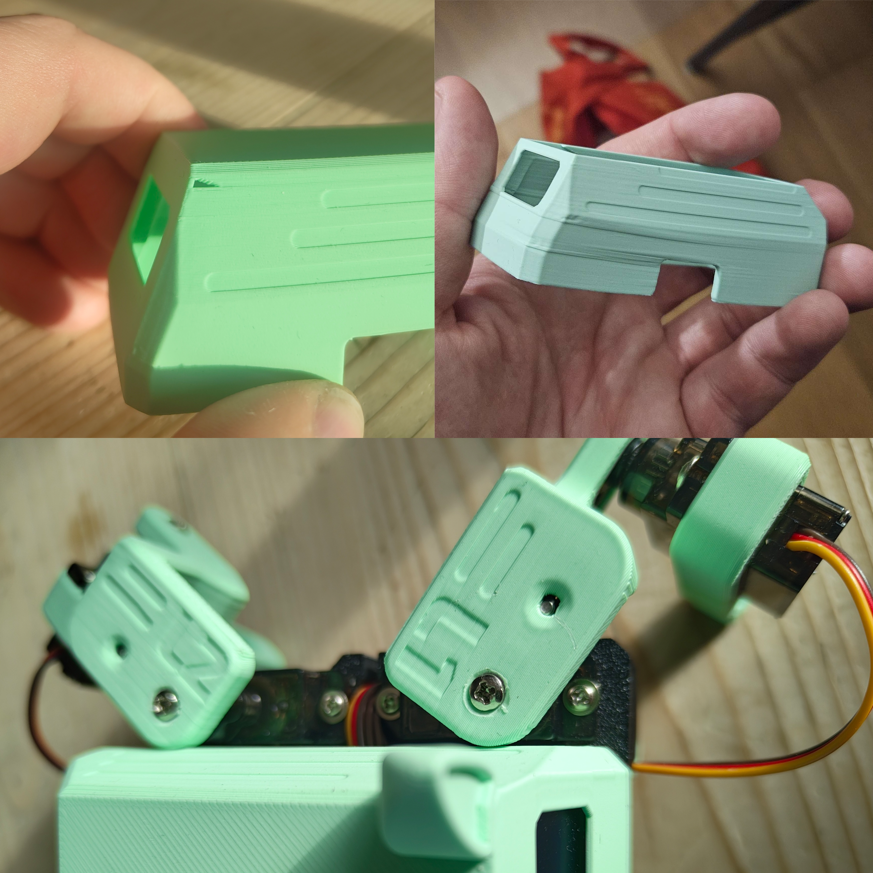
Assembly
Assembly had a surprisingly high amount of adjustments required. A lot of it stemmed from holes being undersized for the self-threading screws, which caused some parts to crack when forced together, or would start to separate layers of the print when the screw reached the bottom of the hole. This was mostly resolved by drilling out the holes to a more reasonable size.
Adjustments
Servo Calibration Workflow
To handle spline alignment and neutral pose consistency, calibration followed this pattern:
- Set all servos to software neutral.
- Mount horns at the closest mechanical match.
- Apply per-joint trim offsets in firmware.
- Re-check leg symmetry on a flat surface.
- Iterate offsets after short walking tests.
Final trim notes:
- Front left: TODO
- Front right: TODO
- Rear left: TODO
- Rear right: TODO
Gait Development
Initial gait goals:
- Stable forward walk.
- Predictable turning.
- Reduced body wobble.
Parameters tuned:
- Step height: TODO
- Stride length: TODO
- Step timing: TODO
- Phase offsets between legs: TODO
Observed behavior after tuning:
- TODO
Results
Current performance snapshot:
- Walking speed: TODO
- Runtime per charge/power setup: TODO
- Turning performance: TODO
- Failure modes still present: TODO
Media to add:
- Short walking clip.
- Close-up of leg motion.
Lessons Learned
- Mechanical tolerances matter more than expected for multi-servo legged robots.
- Small angular errors stack up quickly into visible gait drift.
- Early calibration tooling saves a lot of debugging time later.
- TODO
Next Iteration
Planned improvements:
- Add model clearances around high-friction interfaces.
- Redesign joints for easier assembly and repeatability.
- Improve cable management and serviceability.
- Add closed-loop sensing (for example IMU feedback) for more stable motion.
- TODO
References
- Original project by Dorian Todd: Sesame Robot
- Gait development inspiration by Aaed Musa: I Built a Robot Dog Using… Rope?